Professional SMPTE-2110 Settings
Blackmagic Design 2110 IP Video products are very easy to use and don't require IT specialists because they can be connected point to point. So you can use the Ethernet connections the same way as BNC SDI cables! However, when you start building large SMPTE-2110 systems using network switches, you need a range of settings to get everything working right. Simply use the free utility software to update all these settings. The utility software runs on both Mac and Windows computers. You can update settings for the Grandmaster Clock so all your cameras, switchers and decks can lock to it. You can also set up NMOS routing control and name the senders and receivers to make routing video easy.


2022-7 Redundancy
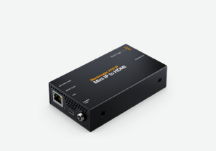
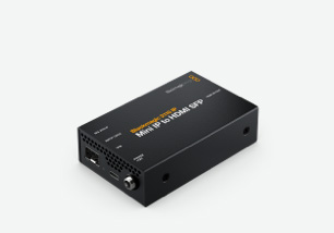
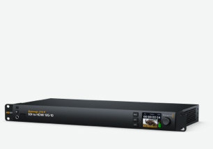
The Blackmagic 2110 IP SDI to HDMI 12G-10 model has 2 separate 10G Ethernet ports, which means it supports SMPTE-2110 redundancy. SMPTE-2110 redundancy sends two identical copies of your video and audio across two separate network connections. This works even better if you connect the redundant Ethernet ports to completely separate Ethernet switches. This redundancy is called SMPTE 2022-7 Seamless Protection Switching and it compares the incoming RTP packets on both Ethernet connections by sequence number and then reconstructs a perfect video frame from whichever packet of pixels arrives first. The switchover is real time and totally seamless with no dropped frames or audio glitches!


Sender and Receiver Settings
The sender and receiver settings configure the products’ role in a SMPTE-2110 system. For example, the sender will package the video, audio, or metadata output and then send them via separate IP streams across your network. Then the receiver does the opposite, where it will "subscribe" to incoming IP streams and reconstruct them as the video input. To set this up, you can define the destination multicast address, port number and stream format for each essence type. So a camera would be a sender while a monitor or switcher input would be a receiver. Correctly configuring these settings ensures your 2110 IP streams reach the right destinations and are decoded properly.

Audio Configuration
The Audio Configuration setting controls how you send and receive audio over SMPTE-2110-30 PCM audio streams. Unlike SDI where audio is embedded into the video, SMPTE-2110 carries audio as independent IP streams. This setting lets you define the number of audio channels per stream, sample rate, bit depth and packet time. You can also map which channels go to which stream, such as a stereo pair on one stream and a 5.1 surround sound mix on another stream. This ensures audio lines up correctly at the receiver and channel assignments match what you need. It's important these settings match between sender and receiver, as mismatches can cause silent channels, swapped audio, or sync problems.

Ancillary Data Identifier
The Ancillary Data Identifier (DID/SDID) setting lets you set which type of ancillary data to embed or extract from a SMPTE-2110-40 stream. In SDI, ancillary data like closed captions, timecode and AFD is embedded into the blanking on the video signal. However, with 2110, ancillary data is sent down its own separate IP stream. The DID and SDID values act as labels identifying what data is carried, such as closed captions, which would use a different identifier than the timecode stream. By setting the correct DID/SDID, your device knows which ancillary packets to decode or to generate, so the right metadata is connected to the right destination.
Timecode
Closed Caption
AFD

NMOS Registry
The NMOS Registry setting is where the central NMOS Registration and Discovery Server is on your network. NMOS is the routing control that works with SMPTE-2110 video and it manages connections between the senders and receivers to route video. Once set up, it "registers" itself using the IS-04 Discovery protocol so other IP video products and controllers can find it and accept connections via IS-05 Connection Management protocol. The NMOS registry is like a phonebook of products on your network where every device checks in, advertises its streams and can then be routed by a control panel. Without an NMOS Registry, it would be impossible to manage and route video in a large 2110 system!

Multicast Address
There are settings to let you customize your multicast addresses for each video, audio, and ancillary stream, so they can be logically grouped by your IP video network. A multicast address is a special IP address with a range from 224.0.0.0 through to 239.255.255.255 that allows one-to-many communication. This efficiently sends video, audio, and ancillary streams to multiple receivers simultaneously. The sender won't need to send the same information to each receiver because it is delegating this task to the network switch, saving on bandwidth and network topology.

PTP Clock Settings
Traditionally, professional video products use tri-sync or black burst as a reference, but SMPTE-2110 IP products use a different reference called Precision Time Protocol or PTP. The utility software has all the settings you need to configure PTP in large broadcast systems. A Grandmaster clock distributes accurate time across the IP network to your cameras, switchers and decks, which lock to it. This ensures video, audio and metadata streams align perfectly at the receiver, even when traveling as independent IP flows. PTP is hierarchical with the Grandmaster at the top, Boundary Clocks in switches relaying timing downstream and PTP clients continuously adjusting to stay synchronized.


Domain Number
The setting for PTP Domain Number lets you set which PTP clock group you want to lock to. Then you will only sync to Grandmasters sharing the same domain, so you can have multiple independent PTP systems coexist on the network.

Master
The PTP Master setting controls whether your device can act as a Grandmaster clock candidate, distributing timing to other devices on the network, or operates as a client that receives time from and locks to an existing Grandmaster.

PTP Lock
The PTP Lock indicator shows whether you have successfully synchronized to a Grandmaster clock on the network. When locked, it means you are receiving accurate timing and ready to process SMPTE-2110 streams in sync with the larger system.

Priority
The PTP Priority setting determines who becomes the Grandmaster when multiple generators exist. A lower value means higher priority. The network uses this during the "Best Master Clock Algorithm" to automatically select the preferred clock source.

Announce Interval and Timeout
PTP Announce Interval sets how often a Grandmaster sends announce messages advertising itself. The timeout defines how many missed intervals before a device assumes the Grandmaster is lost and triggers a new best master clock selection.

Follower Only Mode
When adding a new device, PTP can be sensitive to higher priority clocks, causing the whole network to resynchronize to the new PTP clock. With Blackmagic IP products, you can set the priority to "Follower Only" mode to make sure this never occurs.

Codec Support
In broadcast, the old rule was never touch images unless you absolutely have to! SDI video is great quality because pixels are transmitted uncompressed, untouched and mathematically perfect. With 100G Ethernet, you can get 8 channels of uncompressed video. However, 10G Ethernet is also a fantastic option for IP video because it's very common and low cost. You can even power equipment with PoE! The problem with 10G Ethernet is it lacks the bandwidth required for the two highest rate 2160p59.94 and 2160p60 television standards. To use 10G Ethernet, you can enable the IP10 video codec. The IP10 codec is open standard and lossless, so it lets you use low cost 10G Ethernet for IP video!